Building an RF transmitter amplifier circuit based on a miniBloc, SOT-227B
Amplifier Power MOSFET circuit
This is an F-Class: MegaHertz Switching Power MOSFET.
It is rated for 1000 Volt and 24 A. Maximum, power dissipation is 600 Watt. It is N-channel driven. Switching has to be above 500 KHZ
What do I need?
1. IXYS RF
IXFN24N100F from Element 14 or Farnell.
2. 4 Nylon nuts and bolts, M5 with washers or spacers
3. Metal housing to shield RF interference
4. 2 SO239 housing RF connectors
5. 4mm Cinch female housing connector
6. 1 X 10-15 OHM Iron Clad resistor, 20-50 watt
7. PL-259 plug to BNC, if required
8. Large heat sink for the MOSFET
9. 1mm wire, 50 cm
10. Thermal paste for heat dissipation of the MOSFET
2. Part list
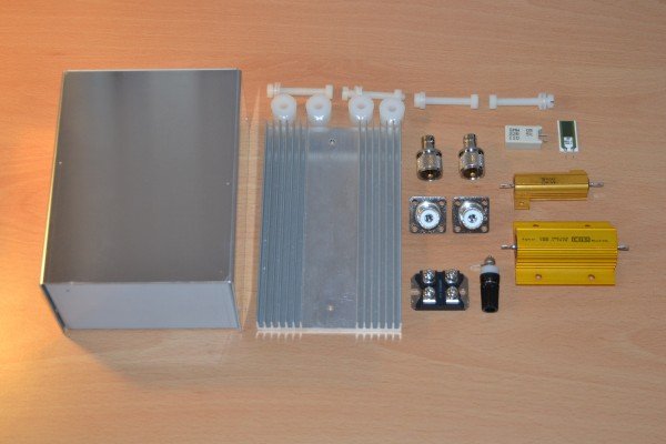
The main parts are listed below. Resistors are as example. You have the IRON Clad, which is funny enough aluminium housing. It is a 10 Ohm, 50 Watt and a 15 Ohm, 100 watt resistor. They are wire wound and can influence the frequency. Above them is a ceramic resistor also wire wound, 20 Ohm and 5 watt and right next to it the only not wire wound carbon resistor. This would be perfect however they come only in low power ratings. I will use the 10 Ohm 50 watt and compensate with a resistor on the plus side of polarity. Important, this is N-Channel based MOSFET. That means the base on a normal MOSFET, N-Channel would have the Drain connected to the base plate. That is not the case here. It is full isolated so no worry to get zapped. I connected it however direct to the heat sink to improve heat dissipation. In order to do so you mount the MOSFET onto the heat sink and isolate it from the housing. You can use Nylon bolts and nuts as listed below or metal screws.
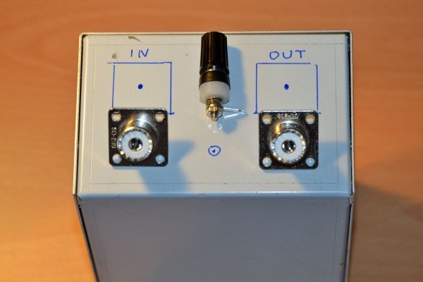
Mark on the case the positions for the mounts. This is my recommendation but you are free to design as you wish. The In connector is getting the signal from the driver. The out goes later to the antenna or coil. The 4 mm female connector is for the neutral of the higher voltage DC power. The MOSFET can take 1000 Volt. I will run it only with 100-120 volt at the beginning.
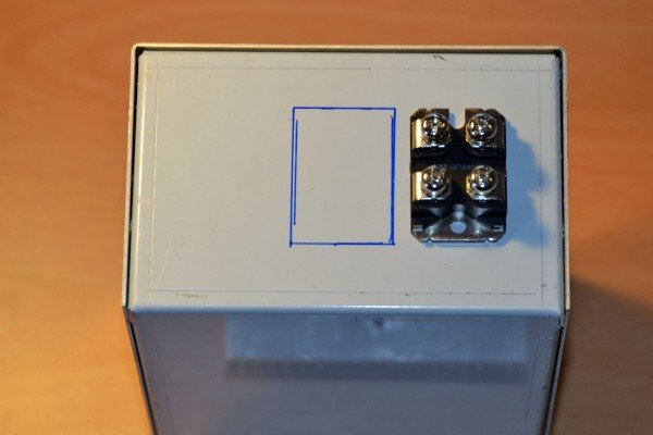
On the opposite side will be the power MOSFET. We mark the position where it will be located on the heat sink. We have to cut this section out of the box.
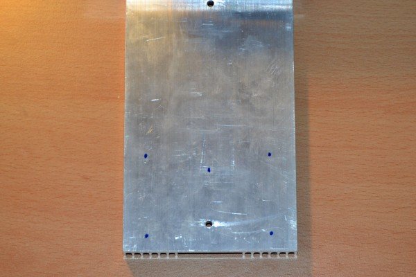
The heat sink need to be drilled for the mount onto the case and for the power MOSFET.
The completed drilling and mount. I did put the 5 watt 10 Ohm resistor in the middle of the case for later use.
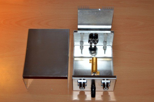
Another close up.
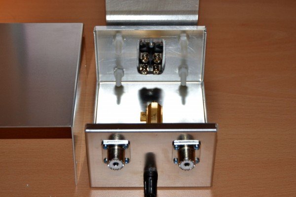
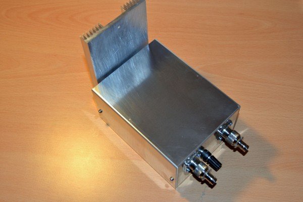
Side view. The heat sink has washers to the case. It is not electrically connected to it and allows good air circulation. The case is earthed via the RF connectors. A separate RF ground connection can be added. The only work left is to connect the wire and it is ready to go. I have connected the BNC adapter to the SO239 mount.
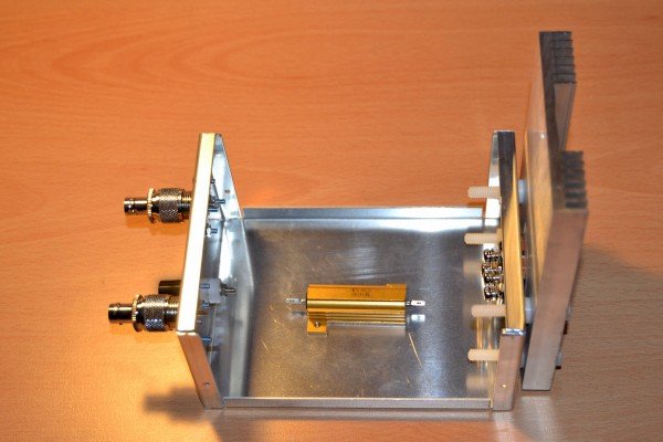
All connections are wired up. For test purpose and security I use the 10 Ohm, 50 Watt resistor in between the Source to Neutral connection.
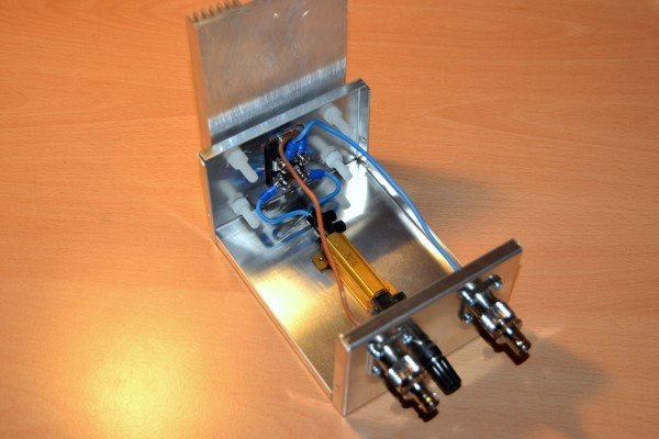
Completed amplifier build. Bear in mind you can connect the heat sink direct to the case. I will test for best heat dissipation and update this section accordingly.
First test did conclude that this amplifier will draw no current unless a proper resonating load is connected. I have used a resonant coil which did not draw much current and after using neon probes on the standing wave of the coil the current draw did increase and so did the output.